Classification
| type | # of discrete variables | # of clocks | # of rest variables | # of controller modes | # of plant modes | # of jumps |
|---|---|---|---|---|---|---|
| original | 0 | 0 | 22 | 20 | 14 | 296 |
| timed | 0 | 2 | 20 | 20 | 14 | 296 |
| discrete | 17 | 0 | 5 | 20 | 14 | 296 |
| timed & discrete | 17 | 2 | 20 | 20 | 14 | 296 |
| Type | Continuous dynamics | Guards & Invariants | Resets |
|---|---|---|---|
| hybrid | constant | hyperplane & half-space | constant |
Download
| SpaceEx | spaceEx_files |
| HyPro | hypro_files |
Model description
This benchmark models the water levels of two water tanks in a closed system. Each tank has a constant inflow and a constant outflow. The tanks are connected via pipes, such that the amount of water outflow of the first tank is equal to the inflow of the second tank and vice versa. One pump per pipe allows to enable/disable the water flow. We add a controller to the two tank system that controls the pumps. A pump is switched off if the water level of the source tank is low ( ) or if the water level of the target tank is high (
 ). Each time a pump is switched off by the controller, the other pump is switched on to balance the water levels in the tanks. The introduction of the controller adds variables to model sensing low and high water levels of both tanks and variables to model the actuator (pump) states in the plant and the controller. Moreover, we add a variable to store the controller mode and a new clock to model the PLC cycle time. We model a user which switches the pumps manually on or off as far as the water levels allow it. We implemented a user that toggles the state of each pump in each PLC cycle. The global time horizon and a PLC cycle time were set to 20 seconds respectively 1 second.
The dynamics of the waterlevel of the tanks is defined by the following differential equations:
![\[\dot{h}_1 = \left\{ \begin{array}{l l} $\phantom{-}0$ & \quad \text{if no water can flow}\\ $\phantom{-}3$ & \quad \text{if water flows from the second to the first tank}\\ $-4$ & \quad \text{if water flows from the first to the second tank}\\ $-1$ & \quad \text{if water flows in both directions}\\ \end{array} \right. \] \[\dot{h}_2 = \left\{ \begin{array}{l l} $\phantom{-}0$ & \quad \text{if no water can flow}\\ $-3$ & \quad \text{if water flows from the second to the first tank}\\ $\phantom{-}4$ & \quad \text{if water flows from the first to the second tank}\\ $\phantom{-}1$ & \quad \text{if water flows in both directions}\\ \end{array} \right. \]](https://ths.rwth-aachen.de/wp-content/ql-cache/quicklatex.com-ca304d4a30b9b5efa12d452b1bd32c0d_l3.png "Rendered by QuickLaTeX.com")
Reachability settings
We consider an initial set of


and the starting location  , a time horizon
  , a PLC cycle duration of
  , and a time step
  .
.
Results
Fig.1 shows the flowpipes computed for the above-mentioned parameters using a) Hypro and b) SpaceEx.
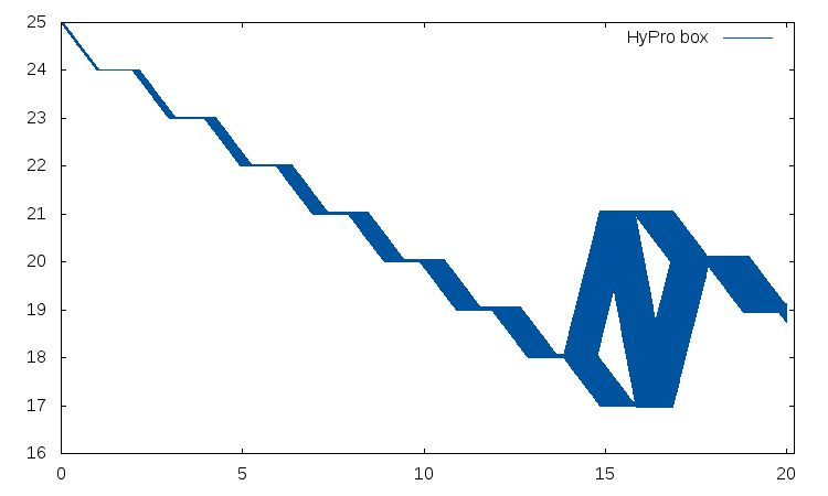
Figure 1: Flowpipe of the two tank system with controller
References
[1] J. Nellen. Analysis and synthesis of hybrid systems in engineering applications. PhD Thesis, RWTH Aachen University, 2016.
[2] S. Schupp et al.. Divide and conquer: Variable set separation in hybrid systems reachability analysis. Submitted to (QAPL’17).